ESP32 LED Controller
Jul 27, 2025
Introduction
This was a fun little project I put together over a couple of weekends. I like reading in bed, but my bedside lamps are either too harsh when pointed at me or too dim when bounced off the wall. So I built a custom PCB to drive WS2812/SK6812 LED strips and mounted them on my bed's headboard using aluminum profiles with plastic diffusers, creating a soft ambient glow across the room.
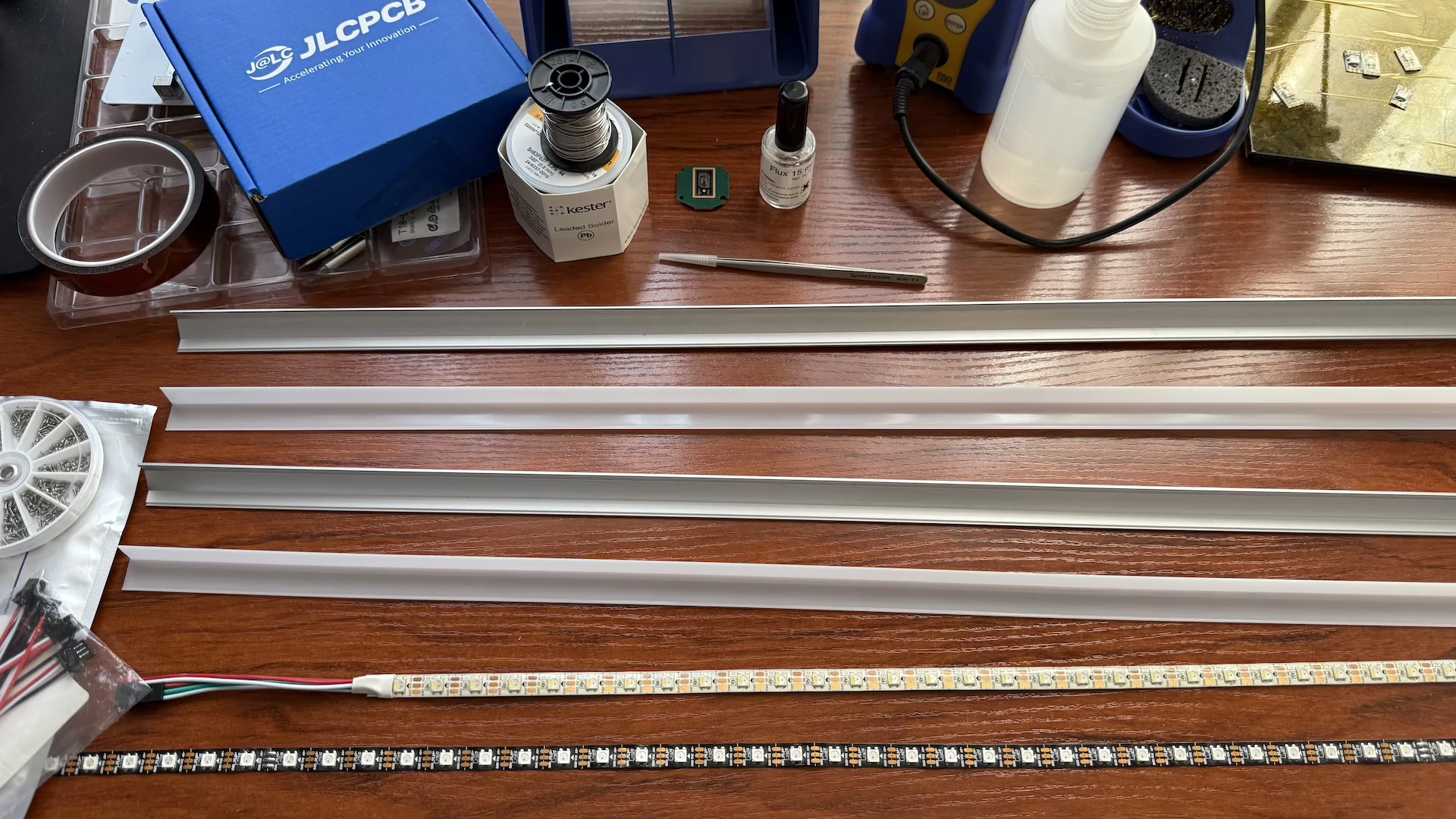 Getting everything ready to assemble the profiles 🪚
I already had some lamps around the house connected to Alexa for simple routines, like turning on gradually in the morning to wake me up and turning off again after a couple of hours. Everything was managed by an Echo Show 5, and I wanted the new LEDs to work with those routines too. I decided to build the controller myself so I could have a local web interface for direct control and avoid relying on third-party apps or cloud services as they tend to shut down, get deprecated, or start charging subscriptions sooner or later. I just wanted something dead simple that runs on the local network and doesn't need updates.
Board Design
The board was designed in KiCad 9. Since I buy most components from LCSC, I always use easyeda2kicad.py, which makes it easy to import footprints and part numbers directly into KiCad. Instead of creating footprints by hand, you can just run a command to get the symbol, footprint, and 3D model into the project:
easyeda2kicad --full --lcsc_id=<Part_ID>
For the microcontroller, I went with an ESP32-S3-WROOM-1-N8 with 8MB of flash. It has Wi-Fi and Bluetooth 5, is easy to program, and works with both the Espressif IDF and Arduino.
Power is supplied through a 2.5mm barrel connector (I already had a 5V@10A power supply laying around) and then stepped down using an LM1117S-3.3 linear voltage regulator for the microcontroller. The LM1117S-3.3 will probably be replaced with a more efficient buck converter in the next revision.
Since the ESP32 outputs 3.3V logic but most LED strips expect 5V signals, I added an SN74AHCT125PWR level shifter. I've found that using a dedicated IC works better than trying to directly drive MOSFETs, which can cause color-shifting issues (I suspect in this case it was because on my tests, the transistors were out-of-spec counterfeits from Aliexpress). This Bi-Directional Logic Level Converter Hookup Guide from SparkFun is a great introduction to level shifting.
The rest of the components are standard passives and a common anode status LED, driven using the ESP32's LEDC peripheral.
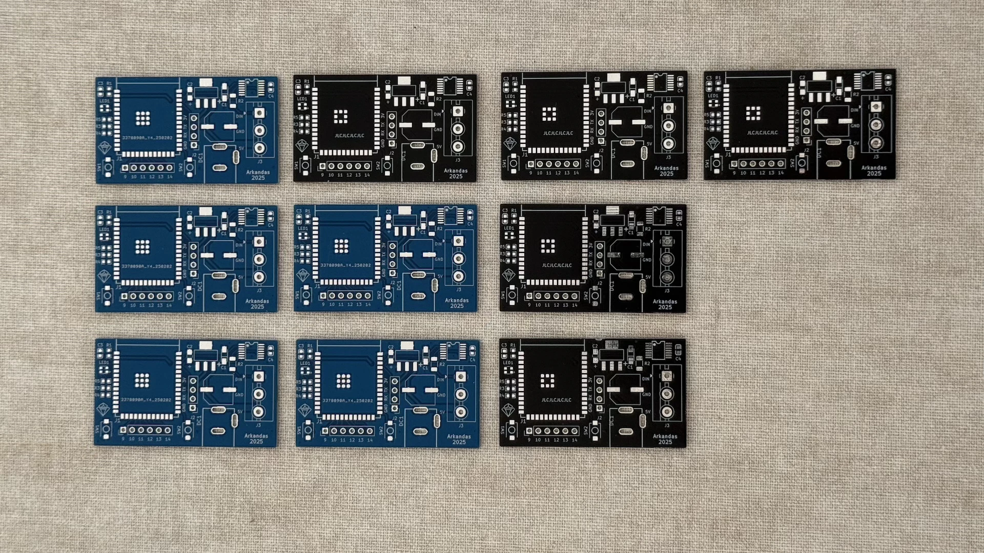
I ordered the first batch of boards from JLCPCB. A set of five cost around €4, shipping included. Their quality has been solid so far. Every board I've received has worked fine, with delivery typically taking about two weeks on their cheapest shipping option.
 Board v0.1 with the wrong GND connection
Right after the first batch shipped, I realized I had used the wrong LM1117 variant. The fixed and adjustable versions have different pinouts, and I had accidentally shorted Vout and GND. Since the PCBs were so cheap, I just updated the design and placed another order, this time with a stencil, instead of trying to rework each board.
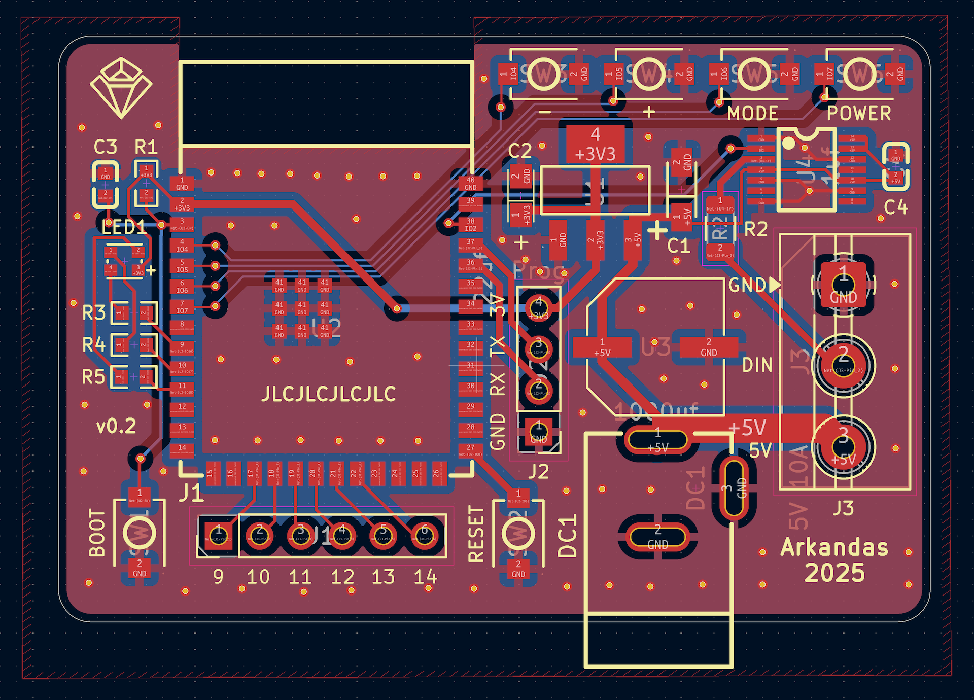 Version 2 PCB layout as seen in KiCad's PCB editor
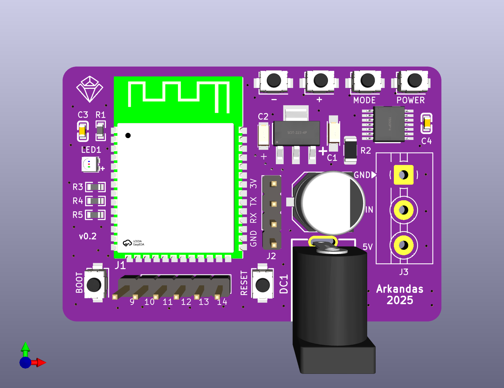 Board preview on Kicad 3D Viewer
📂 Board Files:

PCB Assembly
The main reason I simplified the board design and left out things like a USB port or a CP2102/CH340 UART bridge, which most ESP32 boards have (even though the S3 supports USB OTG and can expose itself as a USB CDC device to be programmed and debugged directly), was to test a cheap soldering hotplate I bought from AliExpress.
I've tried many ways of soldering SMD components, like drag soldering with my Hakko or using a heat gun, but this hotplate was by far the easiest. I used some Chip Quik SMDLTLFP soldering paste, which melts at 138°C, and solder started flowing at about 155-160°C on the hotplate's display. After it was fully heated, I was able to reach around 200°C on the surface.
This type of hotplate is also great for desoldering components from old boards. You only need tweezers and some good quality flux. At around €12 shipped it is a no-brainer for anyone who does any kind of SMD soldering work 👷🏻♂️.
 Cheap AliExpress hotplate used for reflow and desoldering
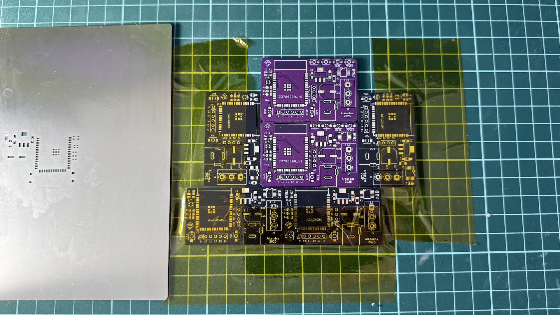 Used the old discarded boards to frame and hold the new one in place. This made applying solder paste with the stencil much easier
Solder paste melting process captured under the microscope 🔬, showing flux and solder particles before liquefying
The board came out great! Just be sure to use a stencil (it's always worth it) and have a solid USB-C power supply for the hotplate, which draws about 65W when heating up.
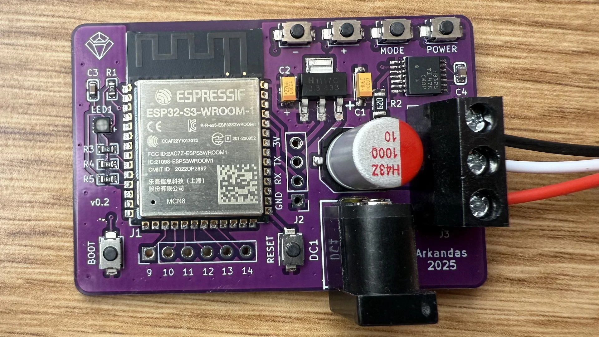 V2 board assembled and ready to roll 🚀
Software
The code is split into two folders: one for WS2812B LEDs using FastLED, and another for SK6812 LEDs using the Adafruit NeoPixel library. The main difference is that SK6812 strips have an extra white LED channel alongside the RGB, which gives true white light instead of having to mix RGB colors (and it looks way better for actual lighting, the W2812B "white" really depends on the quality of your LEDs).
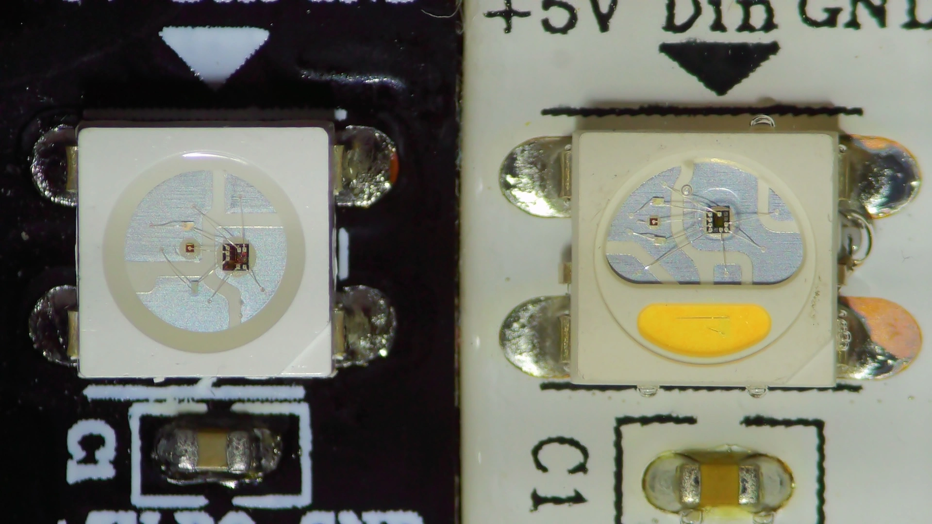 Microscope view of WS2812B (left) and SK6812 (right). Both feature three RGB LEDs sharing a common anode on the left with the controller on the right. The SK6812 also has a white LED at the bottom with two visible wires
Instead of embedding all the HTML, CSS, and JavaScript as CPP strings in the sketch, the web interface files are stored directly on the ESP32's flash using LittleFS. This frees RAM, simplifies updates, and doesn't noticeably impact performance.
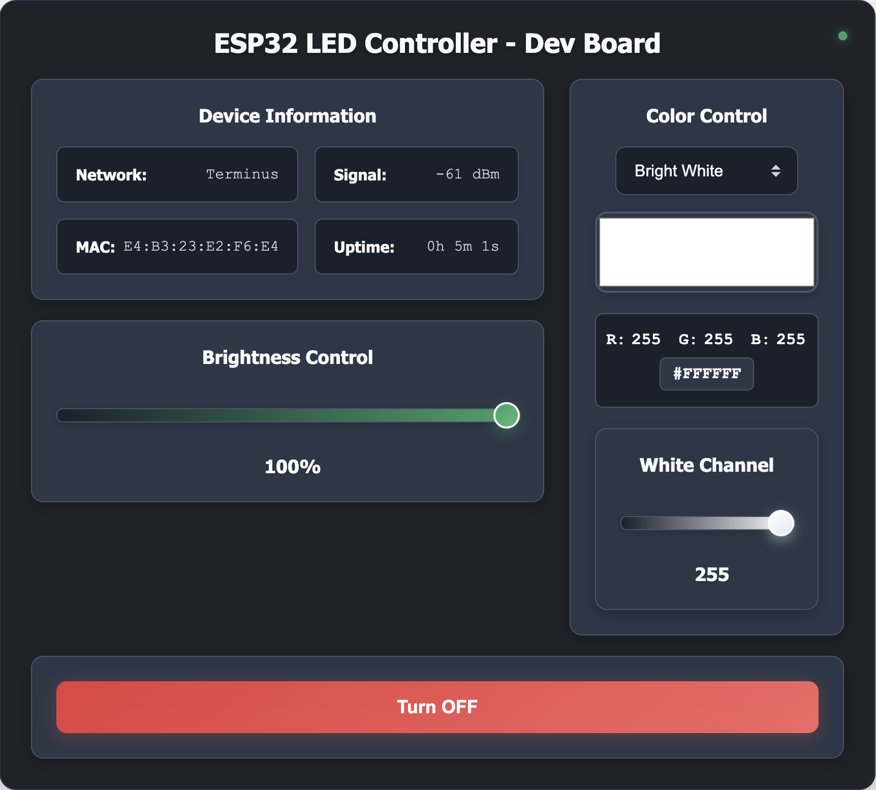 Web interface screenshot
The web interface gives you real-time control with brightness levels, color modes, effects, and for the SK6812 version, individual RGBW channel control.
Setup and Upload
To get this working in Arduino IDE, you first need to add ESP32 support. Go to File → Preferences and add this URL to the Additional Board Manager URLs:
https://raw.githubusercontent.com/espressif/arduino-esp32/gh-pages/package_esp32_index.json
Next, install the ESP32 boards package through the Board Manager and configure it as:
- Board: "ESP32S3 Dev Module"
- Flash Size: "8MB"
- Partition Scheme: "8M with spiffs (3MB APP/1.5MB SPIFFS)"
Make sure the flash size is 8MB and the partition scheme uses SPIFFS to allow space for both the program and the web interface files.
You will also need these libraries from the Library Manager:
- FastLED (for WS2812B) or Adafruit NeoPixel (for SK6812)
- FauxmoESP (for Alexa integration)
- AsyncTCP and ESPAsyncWebServer (both ESP32 versions)
To upload the web interface files, install the Arduino LittleFS Upload plugin.
With LittleFS, the upload process happens in two steps:
- Upload the web files: Place the
datafolder in your sketch directory and use Cmd + Shift + P, then select "Upload LittleFS to Pico/ESP8266/ESP32" - Upload the Arduino sketch: Choose either the WS2812B or SK6812 version, update your WiFi credentials, and upload normally
The ESP32 runs two web servers: one on port 80 for Alexa integration and another on port 8080 for the main web interface.
On startup, both the status LED and the LED strip flash blue while connecting to WiFi, then both flash yellow five times when successfully connected. After that, the status LED stays green at 30% brightness when the strip is on (red when off) and the LEDs turn on with the default color mode.
The board also has 4 physical buttons for manual control: power on/off, brightness up/down, and mode switching. Once everything's connected, you can control the LEDs through the web interface, voice commands, or these physical buttons.
Testing the Controller
Alexa voice commands controlling the LED strip
Web interface controlling the LED strip in real-time
Wrapping Up
I've been testing these new smart lights daily for two months, and they're my favorite DIY project yet. They give perfect lighting for reading, and the Alexa integration just works. The controller hasn't dropped the network yet, and 99% of the time, I run them from my Echo with the same old routines I've had for years.
Given the many ways to improve the current design, I've already ordered two new PCB versions. Both include common upgrades like more efficient step-down converters and a wider voltage input range to support 12V LED strips. The first version adds a USB-C port wired directly to the ESP32-S3 for native USB programming (I miss the auto-reset feature from external UART bridges and want to test TinyUF2). The second version is more of a dev board with two USB-C ports: one for external programming and serial monitoring via a CH343, and one for native USB-OTG, plus extras like a TMP117 temperature sensor for a future IoT Hub project.
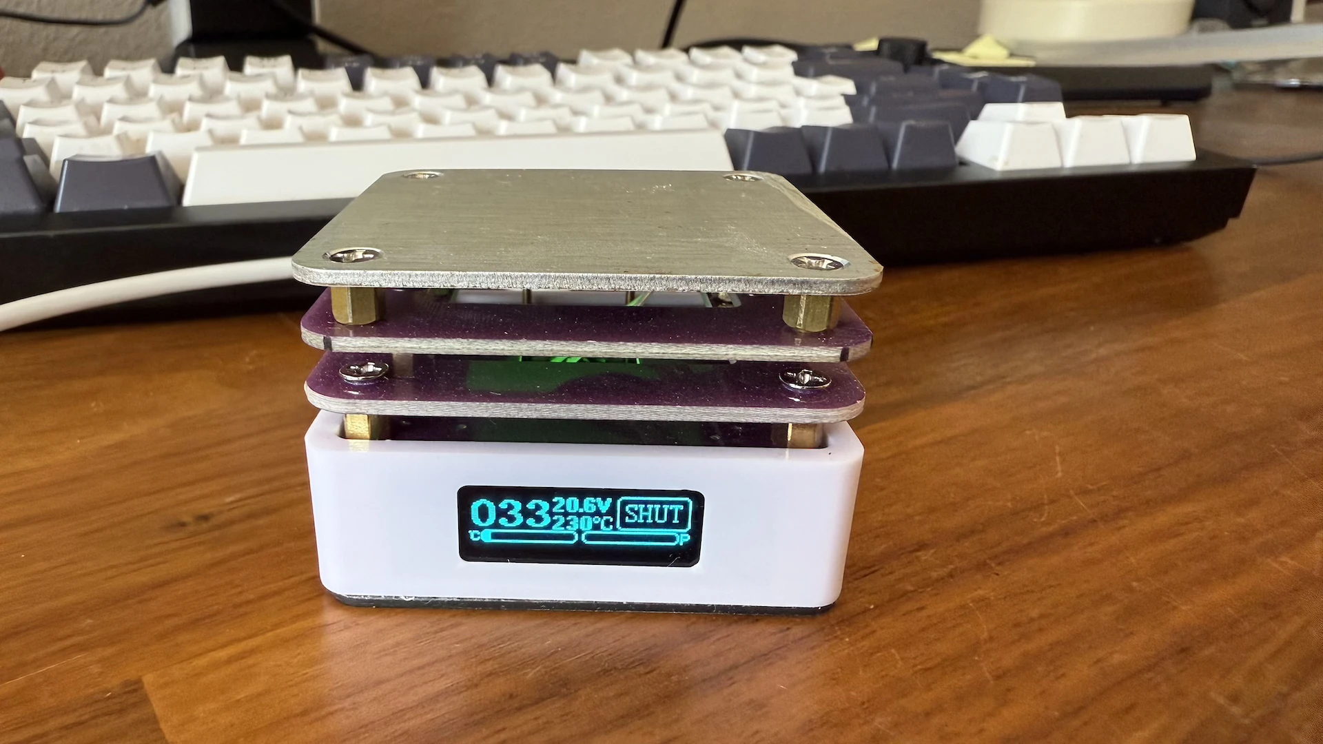
The last upgrade on my list is the mini hot plate. After searching on AliExpress, I chose the IX5 Ultra, which offers a larger soldering surface, better heat control, and clamps to hold the PCB.
Stay tuned for more PCB designs soon! 😉